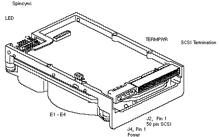
| ID | Jumper |
| 0 | None |
| 1 | E1 |
| 2 | E2 |
| 3 | E1 & E2 |
| 4 | E3 |
| 5 | E1 & E3 |
| 6 | E2 & E3 |
Delay Spin A jumper in the E4 location disables spin up on power-on. Disabling spin up on application of power can also be enabled by setting the DSPN bit in MODE SELECT page 0.
| E4 | DSPN | Result |
| In | 0 | Spin Disabled |
| In | 1 | Spin Disabled |
| Out | 0 | Spin up on Power On |
| Out | 1 | Spin Disabled |

(The table on this page requires NETSCAPE version 1.1 b3 or later to view properly.)
| J4 | |
| 1 | +12V |
| 2 | Ground |
| 3 | Ground |
| 4 | +5V |
| Mounting Holes |
| Side: 6-32 UNC-2B .12 MAX. Insertion |
| Bottom: 6-32 UNC-2B .25 MAX. Insertion |